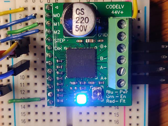
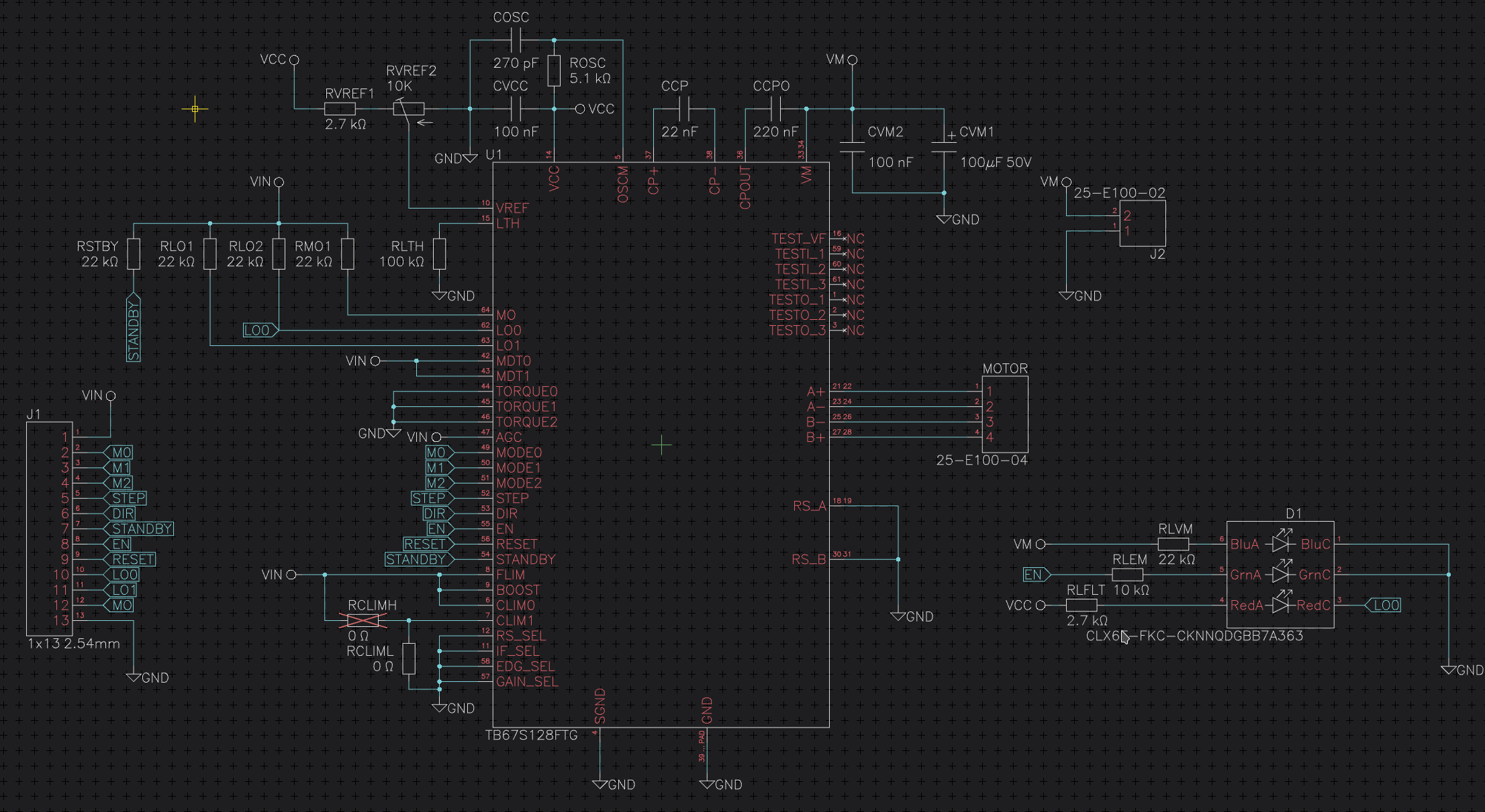
This is a single axis stepper motor breakout board using Toshiba's TB67S128FTG driver.
With proper cooling it can achieve about 2.2A continuous per-phase making it suitable to control most NEMA 17 and NEMA 23 stepper motors in parallel and some smaller NEMA 34 motors in series.
In order to simplify the design several pins have been hard wired to default values.
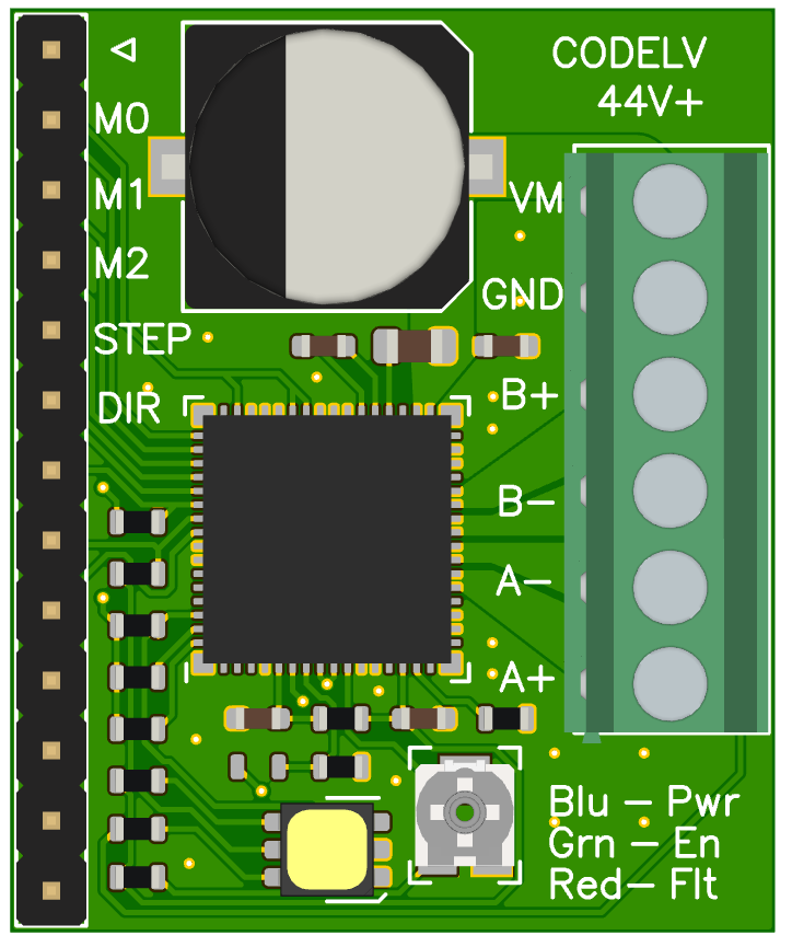
Top of board
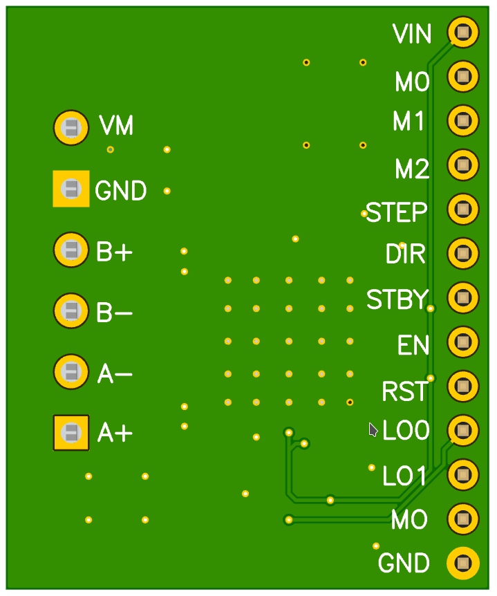
Bottom of board
The minimal setup requires:
Warning: VM has no reverse polarity protection always double check before plugging it in and turning on power!
The board has a trimmer to set VREF. The eval board is hard wired to run in resistor less mode with a gain of 1/5 as shown in section 13.2 of the datasheet.
Ilim = 1.56 * Vref
With the motor disconnected, apply VM and measure the voltage between Vref and ground. The adjustment screw is tied to Vref so you can use that to measure the voltage.
Note: I highly recommend putting a meter in-line with one of the coils to get an actual current reading.
The pins M0 to M2 set the micostepping level. I recommend using the highest resolution your software supports as it will reduce vibration and noise.
| M0 | M1 | M2 | Mode |
|---|---|---|---|
| L | L | L | Full step resolution |
| L | L | H | Half step resolution |
| L | H | L | Quarter step resolution |
| L | H | H | 1/8 step resolution |
| H | L | L | 1/16 step resolution |
| H | L | H | 1/32 step resolution |
| H | H | L | 1/64 step resolution |
| H | H | H | 1/128 step resolution |
Note: Resolution is not the same as accuracy. The torque available changes based on the step angle which can cause positional errors.
The eval board features a RGB led to help you check the status of the driver. The LED will be green when the enable pin is high. When power is applied to VM, the LED will turn blue. If VM has power and is enabled both will be on so the LED will look teal.
If there is a fault on the LO0 pin (such as over current or over temp) the red LED will illuminate, making the LED appear white.
You can check the fault by reading the LO0 and LO1 pins. To reset the fault VM must be cycled or the driver must be put into standby.
| LO0 | LO1 | Error |
|---|---|---|
| Hi-Z | Hi - Z | None |
| Hi-Z | L | Motor open load |
| L | Hi-Z | Over current |
| L | L | Thermal shutdown |
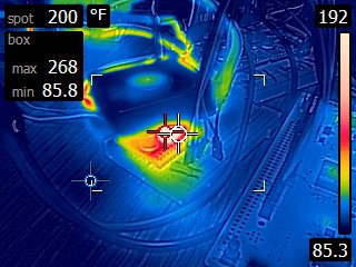
The current continuous current output is highly dependent on cooling.
From my testing, the driver will go thermal shutdown after it reaches about ~315 °F (~160 °C). At high current levels this can happen very shortly.
With fan cooling, continous current levels of slightly above 2A can be achived without thermal shutdown. The following image was taken after about 10 minutes of idling at ~2.05 A.
I designed this using Horizon-EDA. The PCB's were fabbed by JLCPCB. Assembly and reflow is done by me.
I make very little profit (if any) when factoring in my time so please consider donating or sponsoring me if you would like more boards to be made.
Thank you!